Queries, comments, suggestions? Please contact us.


Area Electromagnetism / Electromagnetic concepts and quantities

IEV ref 121-11-77

Symbol
Ψl

en
linked flux
magnetic flux the integration area of which is such that magnetic field lines cross it in the same orientation more than once

Note 1 to entry: Linked flux is observed in two different situations:

1) when the magnetic field is produced by a circuit carrying a current (see Figure 1) and

2) when the magnetic field is produced by an external source (see Figure 2).

Figure 1 – A typical example for linked flux is a coil producing a magnetic flux due to a current i

In Figure 1a), the magnetic field lines (B) link the windings of the coil.

In Figure 1b), the magnetic field lines (B) penetrate the slices of the surface in the same orientation.

The magnetic field of the line closing the circuit is neglected.

Figure 2 – A second typical example for linked flux is a coil in a homogeneous magnetic field represented by the magnetic flux density B varying in time producing an induced voltage U i

In Figure 2a), the magnetic field lines are linked by the windings of the coil (solid lines), the magnetic field outside (dashed lines) is not included in the flux.

In Figure 2b), the magnetic field lines (B) penetrate the slices of the surface in the same orientation.

The magnetic field at the lines closing the circuit is perpendicular to the integration area, and thus the linked flux is zero in this area.

Note 2 to entry: For a coil with N windings, the linked flux is Ψl=NΦ1, where Φ1 is the magnetic flux through a surface corresponding to one average winding, considered to be closed.

Note 3 to entry: The coherent SI unit of linked flux is weber, Wb = kg m2 s−2 A−1.


fr
flux totalisé, m
flux magnétique dont la surface d’intégration est telle que les lignes de champ magnétique la traversent plus d’une fois avec la même orientation

Note 1 à l’article: Le flux totalisé est observé dans deux situations différentes:

1) lorsque le champ magnétique est produit par un circuit traversé par un courant (voir Figure 1) et

2) lorsque le champ magnétique est produit par une source extérieure (voir Figure 2).

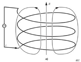
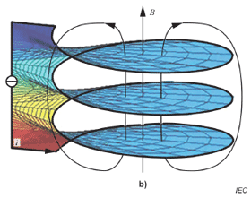
Figure 1 – Un exemple type de flux totalisé est une bobine qui produit un flux magnétique dû à un courant i

Dans la Figure 1a), les lignes de champ magnétique (B) relient les enroulements de la bobine.

Dans la Figure 1b), les lignes de champ magnétique (B) traversent les surfaces avec la même orientation.

Le champ magnétique de la ligne qui ferme le circuit est négligé.

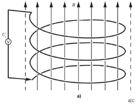
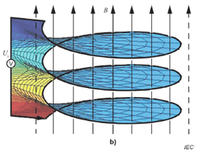
Figure 2 – Un deuxième exemple type de flux totalisé est une bobine dans un champ magnétique homogène représenté par l’induction magnétique B qui varie dans le temps en produisant une tension induite U i

Dans la Figure 2a), les lignes de champ magnétique sont liées par les enroulements de la bobine (lignes pleines), le champ magnétique à l’extérieur (lignes pointillées) n’est pas inclus dans le flux.

Dans la Figure 2b), les lignes de champ magnétique (B) traversent les surfaces avec la même orientation.

Le champ magnétique au niveau des lignes qui ferment le circuit est perpendiculaire à la surface d’intégration, et par conséquent le flux totalisé est nul dans cette surface.

Note 2 à l’article: Pour une bobine à N enroulements, le flux totalisé est Ψl=NΦ1, où Φ1 est le flux magnétique qui traverse une surface correspondant à un enroulement moyen, considéré comme fermé.

Note 3 à l’article: L’unité SI cohérente du flux totalisé est le weber, Wb = kg m2 s−2 A−1.


ar
تدفق مرتبط
فيض مرتبط

de
verketteter Fluss, n

ko
연결자속

ja
鎖交磁束

pl
strumień skojarzony, m

zh
磁通链

Publication date: 2021-03
Copyright © IEC 2024. All Rights Reserved.